Video Transcript
In this QCAD tutorial, we demonstrate the offset tool of QCAD.
Example drawing: offset.dxf
We will learn how to offset single entities such as lines, arcs, circles, ellipses or splines.

We will also cover how to offset entire contours and multiple selected contours.
To begin, we need to access the offset tool.

We can find it in the CAD toolbar under the modification tools.

We can also quickly access the offset tool using the shortcut "O" and "F".

We can enter the desired offset distance in the options toolbar at the top.

For this example, we enter 0.5 for the distance.

If we now move the mouse cursor close to an entity, we can see that the offset entity is displayed as a preview.

If we move the mouse cursor slightly to the other side of the entity, the offset is shown on the other side.
Note that the offset entity will be created on the current layer.

The preview is shown in red here because the current layer has the color red.

We click on the side on which we want to create the offset to draw the offset line.
This same process can be applied to arcs, circles, ellipses and splines.

We simply click the arc, circle, ellipse or spline, while making sure the mouse cursor is on the desired side of the object.

Note that mathematically, the offset curve of an ellipse is not another ellipse but another type of curve.
QCAD creates a spline for this offset curve.

The offset of a spline is created as a polyline with tangentially connected arc segments.

To create multiple offsets at once, we can enter the number of offsets in the options toolbar.

We enter 3 to create three offsets at once.
QCAD offers a second offset tool to draw an offset through a given point.

This offset tool does not require a distance but lets us place the offset using the mouse.
First, we click the entity we want to offset.
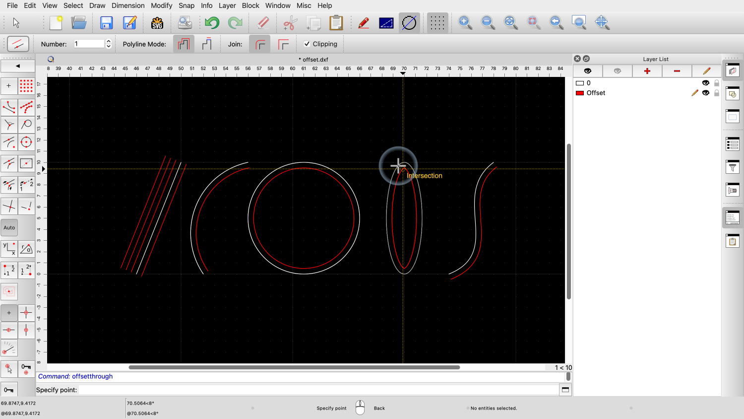
For this tool, it does not matter on which side of the entity the mouse cursor is while clicking the entity.
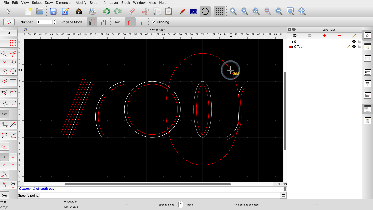
If we now move the mouse, the preview shows that the offset curve will be created through the chosen position.

This allows us to create an offset that goes through a given point.

Another common use of the offset tool is to offset entire contours.
Example drawing: offset_contour.dxf
A contour can be a polyline or any set of connected entities.


This drawing contains a text that has been broken up into polylines.


The border is not a polyline but consists of four separate lines and arcs.

To offset a contour, we use the first offset tool again.


If we click a polyline or a chain of connected entities, QCAD automatically offsets the whole contour.

This works for polylines but also for any shape made up of connected lines, arcs, splines or elliptic arcs.

If we want to offset only one single entity or a single segment of a polyline, we can switch to the polyline segment mode.


In this mode, only the entity or polyline segment we click is offset.

A more advanced use of the offset tool is for offsetting multiple contours at the same time.
Example drawing: offset_contour.dxf

First, we start the offset tool again and check the desired distance and number.

We also switch back to the polyline mode.


If we simply click contours one by one, we end up with overlapping offsets.


We could now manually trim away these overlapping sections.
But QCAD can do this automatically for us.
To do this, we first select all the contours that we want to combine for our offset.
Note that the contours we select for this technique do have to be polylines.
Only the contour we click with the mouse may consist of loosely connected entities.
If in doubt, make sure that all contours involved are closed polylines.

For this example, we select the four letters which all consist of polylines.

Now, we start the offset tool again and click close to one of the selected contours to define the side of the offset.

Since we're only using polylines, it does not matter which one of the contours we click.

QCAD automatically creates a combined offset for all selected polylines.

Note that island contours are also detected and are offset into the opposite direction.

If we combine this technique with multiple offsets, we can fill the space between contours completely with offset polylines.
Example drawing: offset_contour.dxf

For this example, we select everything, including the border.

We choose a smaller distance for this example.

For the number, we enter a number that is large enough to cover the whole space.
QCAD will automatically stop creating offsets when there are no more offsets possible.


We have to click the border in this example, since this contour is not a polyline.
You should now know how to offset entities and contours.
You should also understand the role of the selection when offsetting multiple contours.
Be sure to practice this with your own installation.
Thank you for watching this QCAD tutorial.